Thermal Control
Local seeing in a telescope refers to the degradation of the image quality caused by the presence of the telescope itself. This degradation occurs due to turbulent fluctuations in the refractive index of the air, often caused by temperature gradients between the telescope and its surroundings. Such effects can limit the optical performance of the system and are a primary concern for all modern telescopes.
The European Solar Telescope (EST) is specifically engineered to minimise local seeing. The telescope will be built on top of a 35-meter pier to keep it above the ground layer. Furthermore, its enclosure is completely foldable to facilitate natural air circulation around the telescope. Despite the advantages of this open-air configuration, effective thermal management of all sun-exposed surfaces is necessary. To that end, a combination of passive and active strategies is employed.
The main passive approach –as part of the open-air configuration– is to use specific paint that absorbs only a small fraction of the sun’s energy. Consequently, all external surfaces of EST will be coated in white to minimise heat absorption.
Within the telescope structure, liquid-cooled sun shields are implemented to maintain surface temperatures in line with the local environment, thus reducing temperature gradients inside the optical path. A similar approach is proposed for the telescope platform and the exterior of the enclosure, both directly exposed to the solar radiation. The location of these sun shields has been carefully chosen to balance thermal performance and operational costs. Figure 1 shows in blue the areas selected for active thermal control.
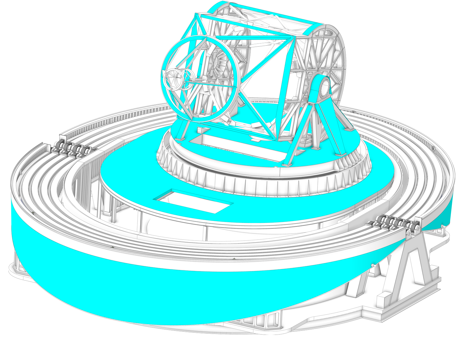
Figure 1. Active thermal control will be applied on the surfaces marked in blue in the image.
The primary mirror (M1) assembly will also benefit from the natural air flushing. However, the thermal load from the sun requires it to be actively cooled. The mirror temperature will be controlled through air impingement jets on its back side, a method chosen for its compatibility with the mirror actuators. The external surfaces of the M1 assembly cell will be temperature-controlled by custom cold plates using liquid coolant. This approach will effectively control the contribution of the primary mirror to local seeing. Figure 2 shows the M1 assembly and the external surfaces with their custom cold plates.
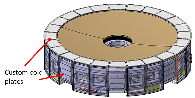
Figure 2. M1 assembly.
The prime focus receives the maximum heat flux density and is placed between the primary and secondary mirrors. To manage this intense heat load, a heat rejecter is strategically located at that point, removing a large fraction of the incoming solar energy. This is possible due to the open-air design of the telescope, which allows the use of a reflecting surface for the heat rejecter. This component reflects most of the energy into the environment, with only a small fraction (approximately 10%) being absorbed. A three-channel cooling coil will remove the absorbed energy. Additive manufacturing will allow optimisation of the heat transfer contact between the refrigerant and the heated surfaces.
The optical elements downstream of the heat rejecter will benefit from a reduced solar heat load. Nevertheless, these components will also be actively cooled to prevent potential contributions to local seeing.