EST Baseline Configuration
EST is a 4.2-metre class solar telescope, in which the primary and secondary mirrors (M1 and M2) are arranged in an on-axis Gregory configuration.
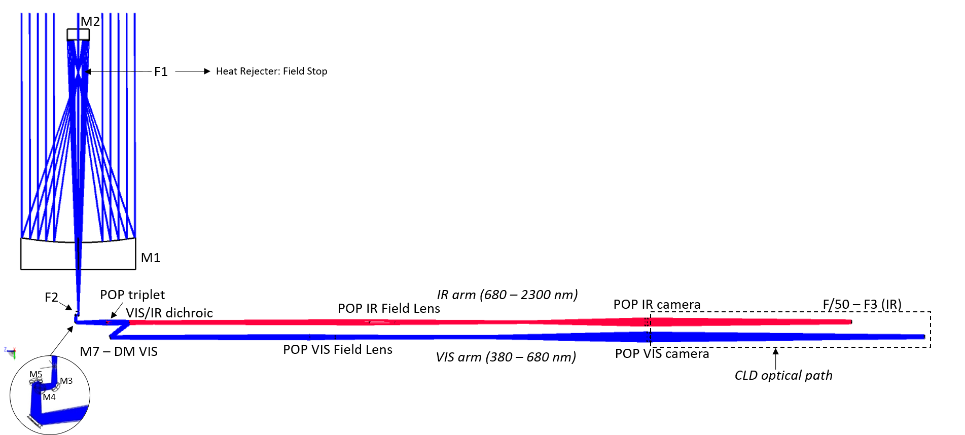
Figure 1. EST Optical Layout
The telescope is followed by four folding mirrors (M3, M4, M5 and M6) that form the Transfer Optics and Calibration Assembly (TOCA). Next, the light traverses a vacuum vessel with a spherical refractive relay system called Pier Optical Path (POP) that generates separate visible and near-infrared science focal panes. A dedicated Coudé Light Distribution (CLD) system is used to further split and transfer the light to each instrument according to wavelength in the two Coudé rooms.
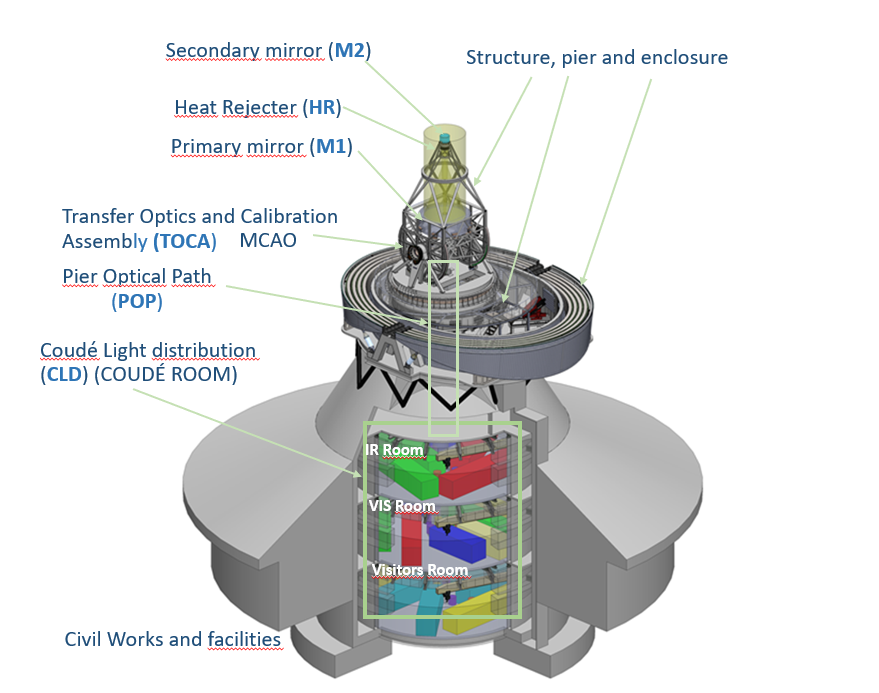
Figure 2. EST Main Systems
The primary mirror (M1) is a solid meniscus with 70 mm thickness supported by 4 rings of tripods. It has the shape of an annulus of 4.2 m external diameter and 1.3 m internal diameter. The M1 support cell includes 80 axial actuators with 3 N/µm stiffness, stroke 10mm, force range +650 / -350 N, force repeatability <±0.2 N and position resolution <0.1µm. Also, there are 20 lateral actuators in tangential configuration with the same characteristics as the axial actuators, but 1:4 lever in order to increase the force range. These elements allows to perform active optics corrections.
The secondary mirror (M2) is a 0.8 m on-axis ellipsoid and defines the whole system aperture stop. M2 is not rigid and is used as an Adaptive Secondary Mirror (ASM). The baseline for the ASM specificies that it should have around 2000 actuators (approximately 50 actuators along the pupil diameter) with a stroke of the order of 16 microns to correct high-order aberrations. The ASM also corrects the image jitter caused by, e.g., atmospheric turbulence, wind disturbance, or vibrations. This image jitter correction is about ±6.5′′ at a bandwidth of 20 Hz and ±1.2′′ at a bandwidth of 350 Hz.
The EST adaptive optics system is integrated in the optical path, both single-and multi-conjugated adaptive optics (SCAO and MCAO, respectively). It uses several deformable mirrors (DM) to provide a corrected image for all science instruments down to the diffraction limit: the ASM acting as M2, M7 at the POP ( which also acts as a DM at a further pupil plane for visible wavelengths in the range 380–680 nm), and the future upgrade of four altitude DMs (M3 to M6). Initially, EST will have SCAO capabilities, using the ASM and M7 as adaptive elements, while the altitude mirrors are kept flat. With the future integration of DMs at the position of M3 to M6, EST will transition to a full MCAO system, enhancing the telescope's capabilities and extending the correction to a wider field of view.
The configuration of the telescope structure is determined by the optical layout. The mechanical structure that holds M1 and M2 has an alt-azimuthal mount. The telescope elevation axis is located below the primary mirror vertex to facilitate M1 air flushing and to provide enough space for the M1 cell and for an adequate placement of the transfer optics. The unusual configuration of the elevation axis below M1 produces a large imbalance around that axis, which is compensated by the part of the structure below M1 and by counterweights. The azimuth and elevation axes are de-centred with respect to the telescope optical axis by the four TOCA mirrors (M3, M4, M5, and M6).
The telescope structure also holds the Heat Rejecter (HR) which consists of a flat cooled mirror, with a tilt angle of 45 degrees with respect to the optical axis. A central hole lets a total field of view of 195 arcseconds go through without any beam vignetting, and ensures that the incoming heat to M2 is lower than 500 W/m2. The energy that cannot be rejected, and is absorbed by the mirror, will be dissipated by a cooling system, to keep the temperature of the reflective surface and the external surfaces of the HR assembly as close as possible to ambient temperature.
The M3-M4 and M5-M6 pairs of mirrors of the TOCA are tilted 45° in perpendicular planes to optimally cancel out the polarization induced by the reflections of the light on them, making the Mueller matrix of the optical system (almost) independent of the telescope pointing.
The enclosure is a rigid fully-retractable dome, designed to facilitate observations in open configuration to allow the circulation of natural air and achieve an optimal seeing performance. The enclosure elliptical design permits the telescope structure to execute short movements when the dome is closed and is compatible with key maintenance procedures that can be carried out under closed enclosure conditions, notably the maintenance manoeuvres for M1 and M2.
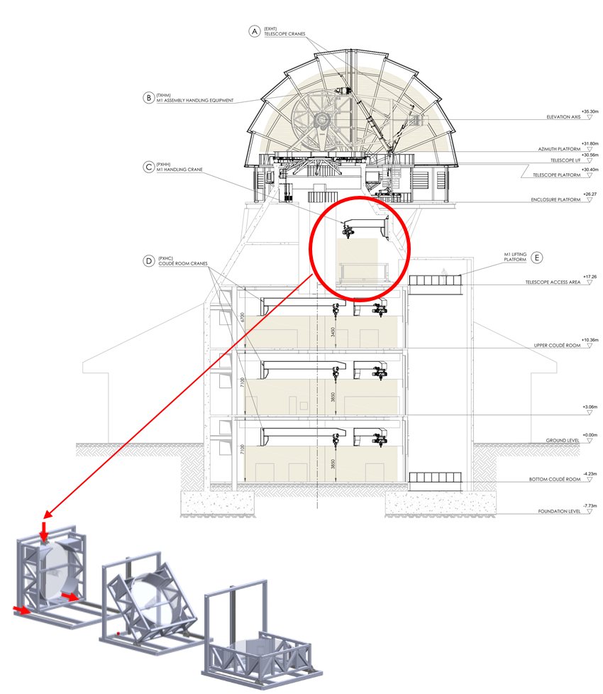
Figure 3. M1 extraction via the pier and detail of the turning tool.
An important advantage of the completely foldable enclosure is that it allows the use of the reflecting heat rejecter at the F1Gregory focus, whereas with a conventional dome it would be necessary to absorb the heat inside the dome.
The drawback of the open-air configuration is the higher wind effect on the image quality produced by wind shaking of the telescope structure and wind buffeting deformation of the primary mirror. The exposure to the Sun, daily temperature variations and wind were key aspects that drove the preliminary design of M1.
The telescope is placed on the top of a pier to improve the local seeing conditions. The pier is a reinforced concrete structure featuring a platform upheld by steel profiles, designed to accommodate the telescope and enclosure. It serves as a foundation for the telescope structure, enclosure, and associated auxiliary equipment, facilitated through the maintenance platform.
Below the telescope platform, the pier transitions into a truncated cone shape, designed to minimise disruptions in airflow. This shape has been meticulously chosen to effectively distribute the telescope's loads to the exterior of the pier and culminates in a crowning beam with a diameter of 8.4 metres. Eventually the pier adopts a cylindrical form (which encompasses the Coudé rooms with all the instruments at the pier base), optimising the space within the enclosure volume.
In the pier, the Coudé Rooms are distributed over two floors: the upper floor houses the infrared (IR) instrumentation and the middle floor the visible (VIS) instrumentation. There is also a third floor to accommodate visitor instruments in the future.
The instruments will be operated in a controlled environment. To fulfill the scientific goals of EST, two types of instruments are planned: (1) Tunable Image Spectropolarimeters based on Fabry-Perot Interferometers and Fixed-Band Imagers (TIS/FBIs); and (2) grating spectropolarimeters based on different Integral Field technologies: microlens arrays (IFS-M) and image slicers (IFS-S). Each of these instruments will measure the polarisation state of the light in selected spectral lines, making it possible to observe and diagnose different layers of the solar atmosphere simultaneously through a sophisticated Coudé Light Distribution system (see Figure 3).
The CLD has been designed to deliver the science focus at specific positions in the Coudé Rooms in order to feed the Scientific Instrumentation Suite (SIS) and the Coudé Sensing Assemblies (CSA) . integrated by sensing instrumentation for the Adaptive Optics (AO) system, the calibration of the telescope and daily observations. There is an assembly in each Coudé room, designated as Coudé Vis/Red Sensing Assembly.
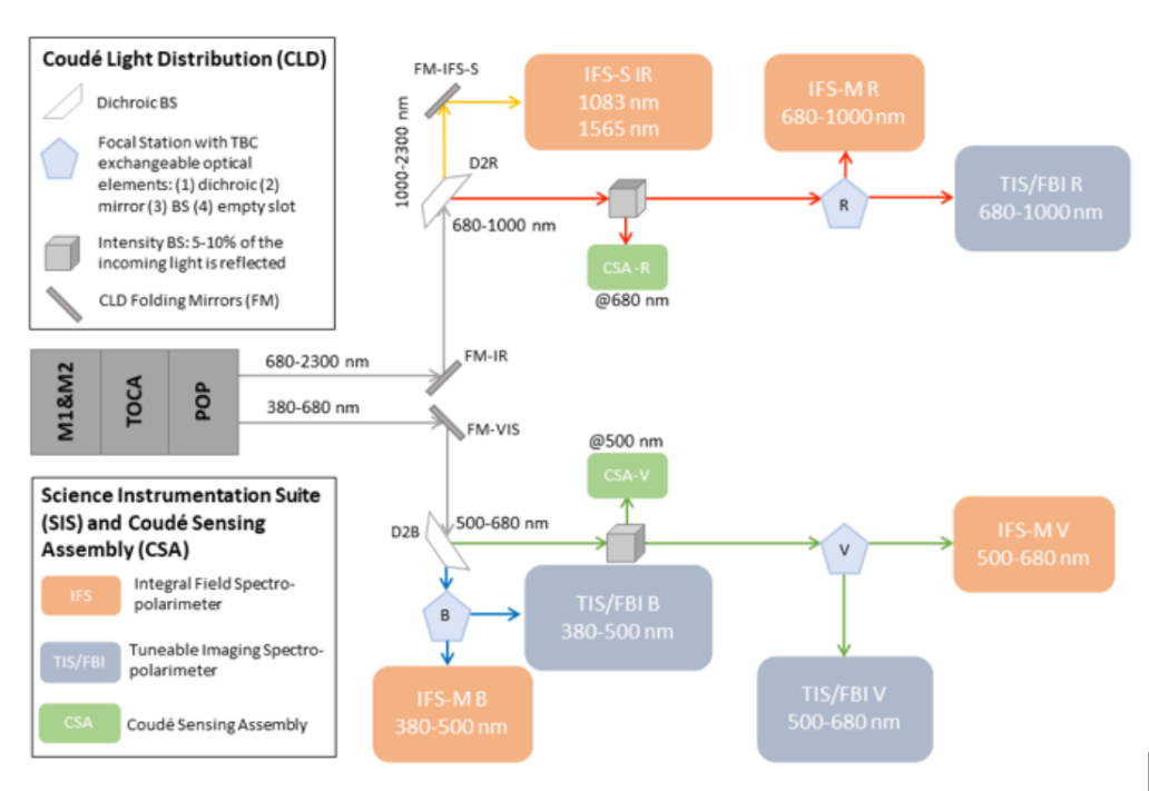
Figure 4. Science Instrumentation Suite (SIS) and Coudé Sensing Assembly (CSA).
A building containing the required control and support installations and facilities will be attached to the tower, providing access to the telescope pier. An additional auxiliary building, containing the facilities that might otherwise degrade the telescope performance through vibrations or air heating, such as the power plant, pumps or water coolers, will be placed far enough from the telescope tower to avoid local seeing disturbances.
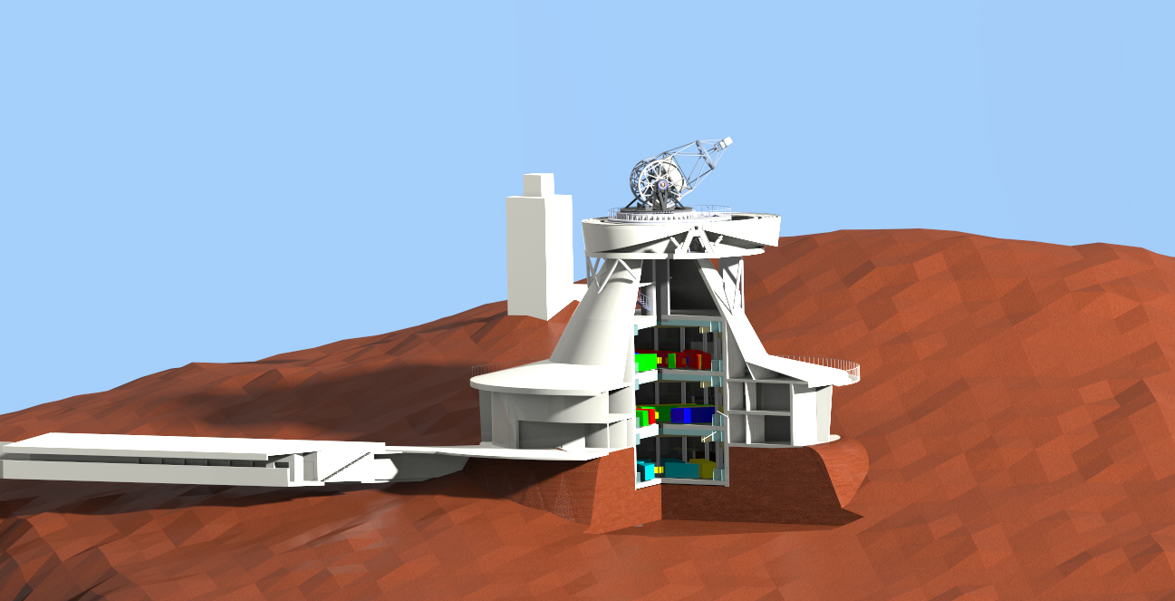
Figure 5. General view of the EST buildings.
The EST facilities will include an auxiliary full disc telescope that will be used to give the observer a global context of the solar activity and precise coordinate measurements.
The operation of the EST infrastructure, as well as the supervision of all its sub-systems, will be carried out by the EST Control System (ECS). The ECS is designed as a distributed system formed by a set of independent nodes that are interconnected by the ECS network.
