The light collected by EST will be distributed to the various scientific instruments through a complex Coudé Light Distribution System (CLD) which is described below.
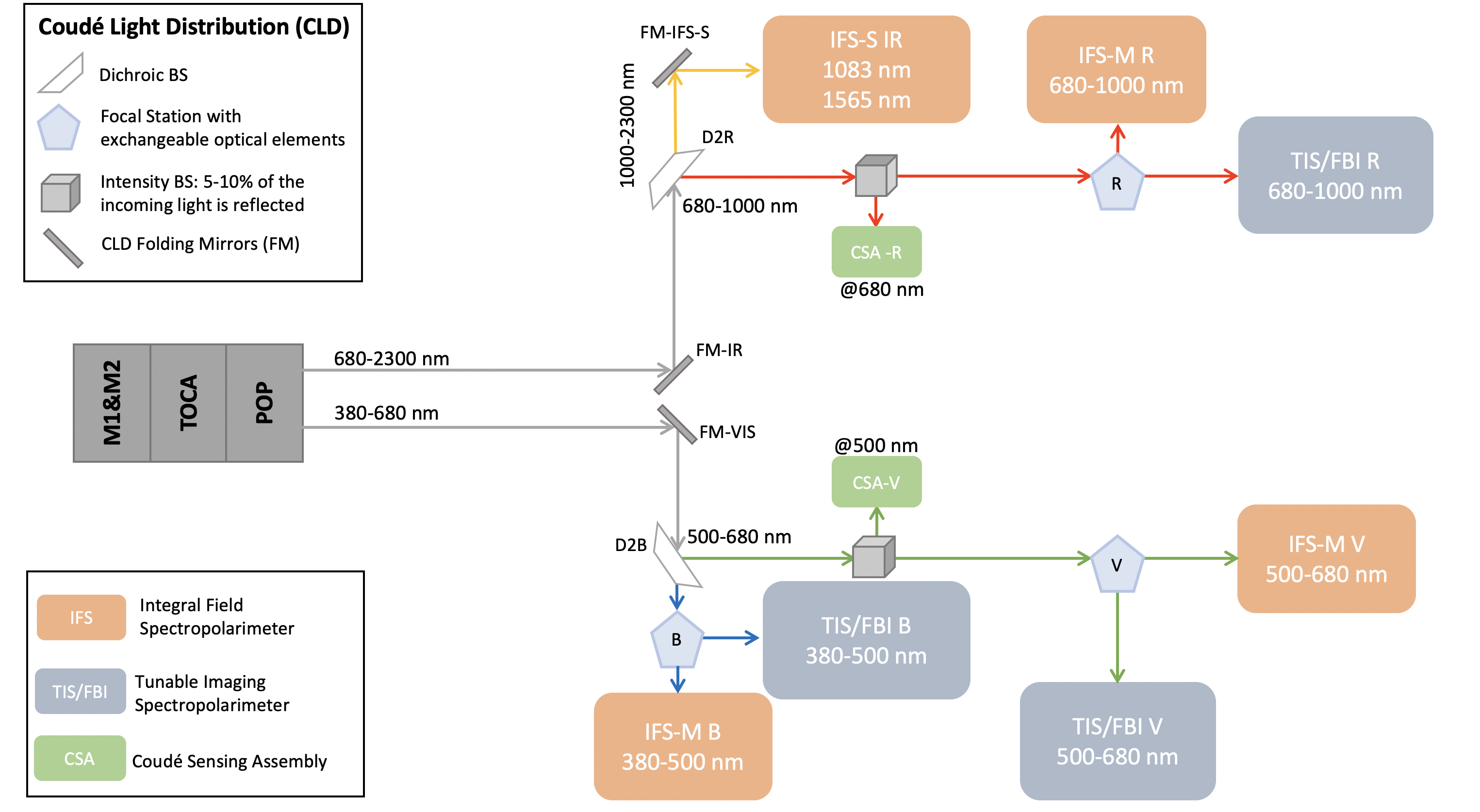 Figure 1. Coudé Light Distribution and Science Instrument Suite diagram.
One of the main goals of EST is to clarify the origin of the magnetic processes taking place in the solar atmosphere. This goal is a top-level requirement to perform simultaneous spectro-polarimetric measurements in multiple spectral lines. For this purpose, EST will be equipped with a set of instruments working simultaneously in different spectral ranges:
- Tunable Imaging Spectropolarimeters based on Fabry-Pérot interferometers, coupled to Fixed-Band Imagers (TIS/FBIs).
- Integral Field Spectropolarimeters based on different technologies: micro-lens arrays (IFS-M) and image slicers (IFS-S).
In addition to the science instruments, the Coudé Sensing Assembly (CSA), which is part of the telescope's Adaptive Optics system, will also be installed in the Coudé rooms.
Once the light from the telescope has passed through the various subsystems, it is split at the Pier Optical Path (POP) level into the visible (380-680 nm) and infrared (680-2300 nm) arms, hereafter referred to as VIS and IR arms, respectively. Also, the POP lenses provide a telecentric science focus that reaches the Coudé rooms where the instruments are installed: the upper floor is reserved for IR instruments, the middle floor for VIS instruments and the ground floor for future guest instruments. The optical elements that form the Coudé Light Distribution (CLD) system are strategically distributed across the Coudé rooms, providing each instrument with a tailored Coudé focus that matches its specific spectral requirements.
The CLD comprises both fixed and interchangeable optical components, allowing the flexibility to generate the required operating modes for the science instrument suite (see diagram in Figure 1).
Two fixed dichroic beam splitters in the VIS and IR arms divide the light into four spectral sub-arms:
- D2B splits the light of the VIS arm into Blue (B) and Visible (V) sub-arms ranging from 380 to 500 nm and 500 to 680 nm, respectively.
- D2R splits the light of the IR arm into Red (R) and Infrared (IR) sub-arms ranging from 680 to 1000 nm and 1000 to 2300 nm respectively.
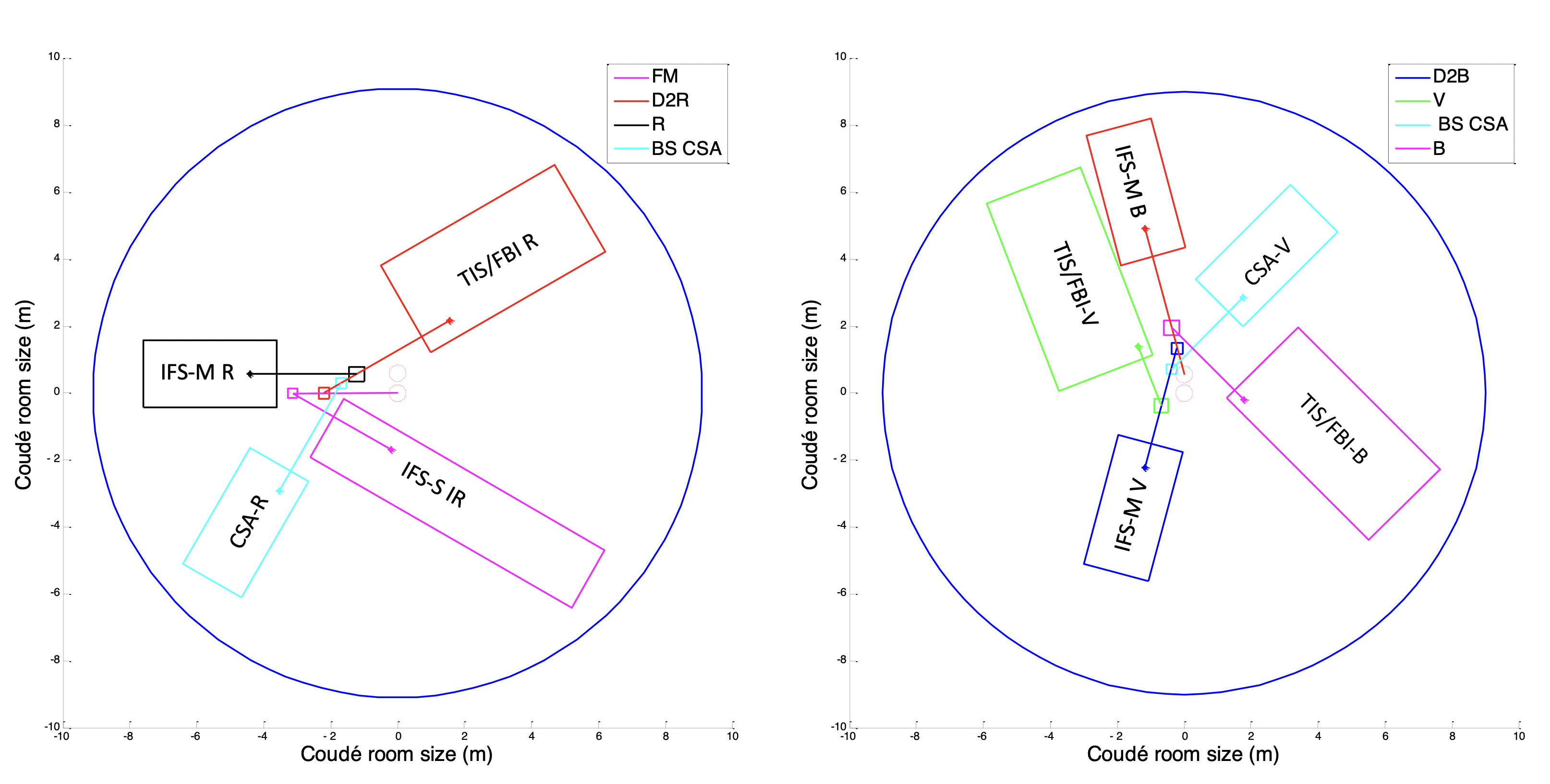 Figure 2. Instrument layout and elements of the Coudé Light Distribution in the IR and VIS Coudé rooms (left and right panels).
The Blue (B), Visible (V), and Red (R) sub-arms each accommodate a focal station equipped with interchangeable optical elements, including mirrors, beam splitters, dichroic filters, plates, and empty slots. This setup enables two different observing modes.
In single operation mode, all the light across the full wavelength range of a sub-arm will be directed to a single type of instrument using a mirror, a plate, or an empty slot.
In dual operation mode, however, the light across the full wavelength range of a sub-arm can be split in two different ways: (a) all the light within a specific wavelength range is directed to one instrument, and the light ouside of that range goes to another instrument using a dichroic filter; or (b) all the light within the sub-arm is directed to the different instruments with different intensities, using an amplitude beam splitter.
The observation programs proposed by the scientific community through the EST Science Requirements Document can be accomplished with 5 filters in the B focal station, 7 in the V focal station, and 4 in the R focal station.
The IR sub-arm hosts only an IFS-S instrument called EMBER that will permanently use the full intensity and spectral range provided by this optical branch (1000-2300 nm) during all scientific operations.
Finally, the V and R sub-arms host the CSA that is part of the AO system required at EST system level. The R and V CSAs will work around 500 nm and 680 nm, respectively, picking 4-6% of the incoming light by means of an intensity beam splitter or a plate by Fresnel reflection.
The CLD is designed to maximise throughput while preserving the optical quality. To achieve this, the number of optical surfaces has been minimised. Furthermore, the angle of incidence on the optical elements is carefully controlled to minimise astigmatism and polarisation effects.
The optical filters are placed in a converging beam resulting in a footprint size ranging from 190 mm to 220 mm. In the preliminary CLD design, all substrates are fused silica plates incorporating a wedge to avoid parasitic reflections and interference fringes. The optical quality specifications are stringent to minimise non-common path wavefront errors that cannot be compensated by the AO system. The coatings of each filter, which are intended to ensure high efficiency at the specific observing wavelengths, are under study with manufacturers. Some filters will require an efficiency spectral profile with a very narrow slope to meet these specifications, necessitating extremely precise design and manufacturing.
The mirrors are specified to be made of Zerodur, coated with protective silver in the IR arm and with UV-enhanced silver in the VIS arm.
The position of each optical element within the Coudé rooms ensures sufficient clearance to accommodate the optomechanical mounts and avoid beam vignetting. Furthermore, the CLD is being adjusted to accommodate the envelopes and input beam positions required by the instruments, as shown in Figure 2.