The adaptive optics strategy adopted for EST at first light is described below, together with simulation results aimed at validating it.
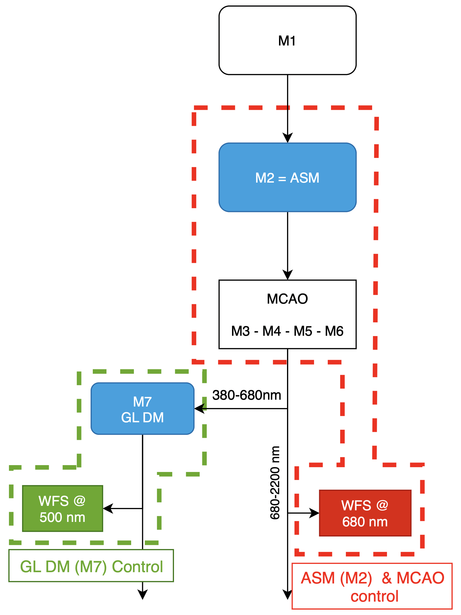 Figure 1. EST AO configuration. The ASM plus red WFS constitutes a first control loop (red). M7 plus the visible WFS provide a second loop (green).
The European Solar Telescope (EST) will include an advanced adaptive optics (AO) system, a cutting-edge technology designed to counteract image distortions caused mainly by the Earth's atmosphere. In the initial first-light configuration, EST will implement a near classic AO setup, with a corrected field of view limited by the atmosphere. EST will integrate two deformable mirrors, one per spectral arm of the Pier Optical Path (POP). Once tested and calibrated, EST will be in conditions to progress into a more sophisticated multi-conjugated adaptive optics (MCAO) arrangement capable of compensating atmospheric disturbances across a broader 60-arcsecond field of view. This article is about the first-light configuration.
The initial configuration includes an adaptive secondary mirror (ASM), managed by a wavefront sensor (WFS) in the infrared Coudé room. A second deformable mirror (M7), placed in the visible spectral arm of the POP, will be controlled by a wavefront sensor in the visible Coudé room. Both sensors are correlating Shack-Hartmann sensors. The second control loop will receive an image already corrected at 680 nm and its purpose is to optimise the correction at 500 nm. To enhance performance, the system will feature a fast tip-tilt camera and a wide-field camera for telescope calibration and image quality assessment.
Having a deformable mirror in each spectral arm has three main advantages for EST compared to having only one. Firstly, the different atmospheric wavefront errors at different wavelengths caused by chromatic anisoplanatism when the telescope is pointing below 25° elevation will be compensated separately. Secondly, each deformable mirror compensates local seeing and vibrations specific for each Coudé instrument room. Finally, the deformable M7 will be faster that the adaptive secondary mirror, as needed for the visible arm.
The adaptive secondary mirror allows reducing the number of optical surfaces but it was identified as a risky development. For that reason a preliminary design has been requested to two different companies, TNO and Adoptica. TNO started earlier and has already ended the design, while Adoptica started at a later time and will conclude the work in 2025. Both designs include a representative prototype that the EST engineering team will compare in the laboratory under the same conditions. Finally, a technical recommendation to go for one company or the other will be issued.
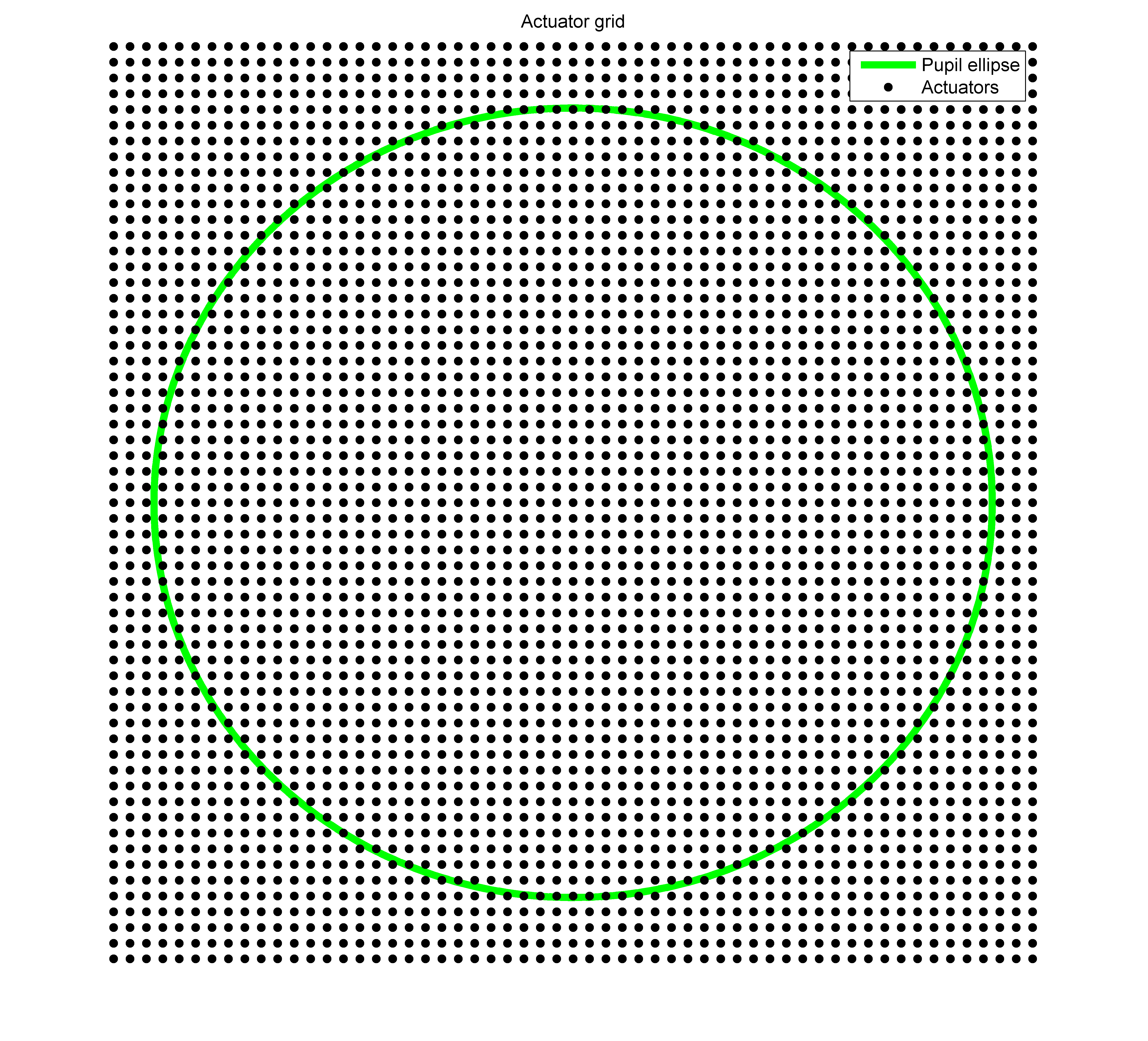
Figure 2. M7 deforable mirror actuator pattern.
In the visible arm, a deformable mirror appropriately sized for the working wavelength of 500 nm is needed. This mirror, known as M7, will have an slightly elliptical optical aperture and will include about 2000 actuators (Figure 2). It will be able to work under vacuum conditions and its electronics will be able to receive and process 2000 commands per second.
In order to achieve diffraction limited observations, it is of utmost importance to have good image stability. Image stability is disturbed mainly by the atmosphere, by wind buffeting over the telescope structure and by mechanical vibrations produced by the telescope itself. Among them, vibrations are expected to be the more challenging disturbance to compensate, particularly those at frequencies higher that 40 Hz. For that reason, an integral plan for vibrations is being prepared that combines two different aspects. Firstly, the telescope design minimises the amount of vibrations that are produced. Secondly, a fast tip-tilt camera that can run at up to 4000 frames per second is foreseen, to reduce the time delay in the control loop and extend the adaptive optics to higher frequencies.
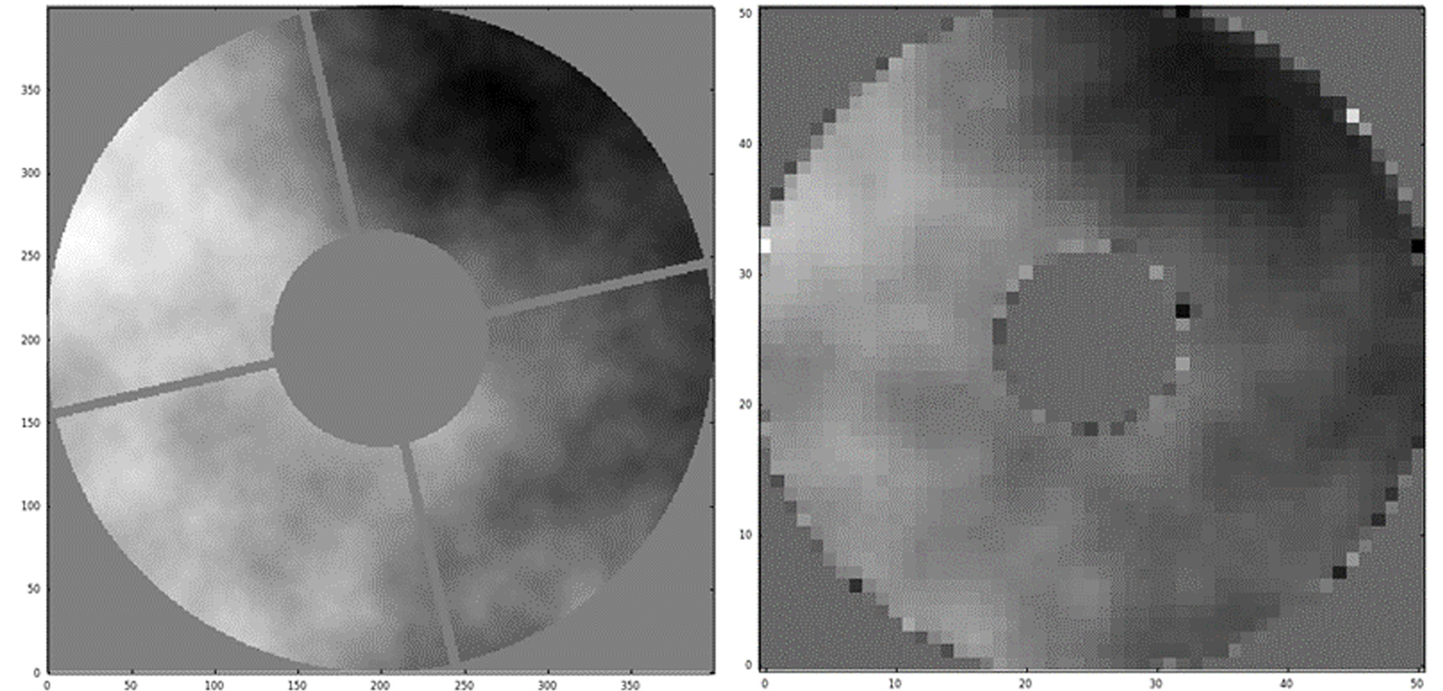
Figure 3. Simulation results for an atmospheric seeing of r0= 7 cm. Left: Turbulence projected in the pupil plane showing the central obscuration and the spider rotated 13º. Right: The corresponding phase reconstructed by the EST AO closing the loop.
To verify its feaibility, the proposed adaptive optics configuration has been tested using the DASP simulator from the University of Durham (UK). The simulations include the central obscuration of the entrance pupil due to the M2 projection over M1 and also the shadowing of the 4 arms of the M2 support over the entrance pupil. The results of the simulations show that, despite these effects, the EST adaptive optics will be capable of reconstructing the phase, and hence to compensate the atmosphere (see Figure 3). The simulations also verified that the two control loops represented in Figure 1 can be used simultaneously in stable operation.